DEAERATOR IN THERMAL POWER PLANT
DEAERATOR AN INTRODUCTION
- Remove dissolved gases.
- Highest vessel in the system.
- Used for heating of feed water.
- Reduce the amount of steam in the system and hence energy flow to the plant.
- Extraction steam enters from the bottom of the tanks.
- Steam passes over the water droplets.
- As the extraction steam condensed the water droplets releases the non-condensable gases vented to the atmosphere.
- The deaerated feedwater & condensed steam mixed and drained out to the FST.
- FST supplies feed water to the boiler feed pumps.
- Acted as an open-type feedwater heater.
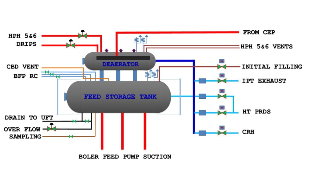
CONNECTION
- One pipeline coming from CEP discharge via through ejectors, GSC D/R coolers LPH-1, 2, 3 which supply the water to the Deaerator.
- Two pipelines are connected to the Deaerator which are coming from HPH-5 & HPH -6 drips.
- Two vent pipelines are connected to the Deaerator tank coming from HPH-5 & HPH-6 shell vents. (Since they have high pressure and high temperature i.e. high energy vent so it is supplied to the Deaerator, for saving DM water and utilization of its energy).
- Three lines (in various plant one line) for the boiler feed pump suction for supplying water to BFP (TDBFP & MDBFP).
- Three lines are connected to the FST which recirculates the water tapped from the discharge line of the boiler feedwater pump (for maintaining minimum flow for BFP),(TDBFP & MDBFP).
- One Deaerator drain line connected which further goes to the unit flash tank and goes to drain out.
- One deaerator overflow line goes to the LPDFT tank (excess water overflow through this line and goes to hot well).
- On deaerator sampling line which is used for sampling of water.
- A initial heating line to the FST water from the steam taken from LT PRDS.
- Deaerator extraction line coming through the extraction of IPT (this steam is used as deaerating steam).
- A line from CRH supply the steam for Deaerating.*(* all these three lines are connected through a common header and then goes to the deaerator but from HTPRDS before the supply valve a line is tapped for initial heating of water into the FST).
- A-line for initial filling is connected to FST for initial filling of FST (it save the energy if filled by CEP).
- A manhole is provided for overhauling and maintenance work in both Deaerator & FST.
- Two standpipes are connected for installments of level transmitters and local gauge glass ( for measuring of the level of deaerator ).
- Also some instruments are installed for temperature, pressure measurement of the system.
DEAERATOR SCHEME
Related Posts
Forces on Steam Turbine Rotor
Topic: Forces on Rotor (Steam Turbine / Turbo-generator Rotor) The paragraph describes the various stressesRead More
Use of MEKO (Methyl Ethyl Ketoxime) Instead of Hydrazine in Boiler Water Treatment
Hydrazine (N₂H₄) has been traditionally used as an oxygen scavenger in boiler feedwater to preventRead More
Explain the types of tube failure that may occur innthe initial stage of boiler operation till stabilization?
During the initial stage of boiler operation, until the system reaches a stable operational phase,Read More
Comments are Closed